Concepts:
Map projections involve the transference of data from a three dimensional model of the earth, a globe, to a two-dimensional surface, a piece of paper. The reason for doing this is that a globe is hard to carry in your pocket, and globes are of too small a scale to show great detail. Where a globe is presumably a perfect model of the earth, meaning that distance, location, direction, size (area), shape, and everything else are correct, a map is NOT perfect. The projection process causes various forms of distortion. If projection causes distortion, then why must we project?Why Project?
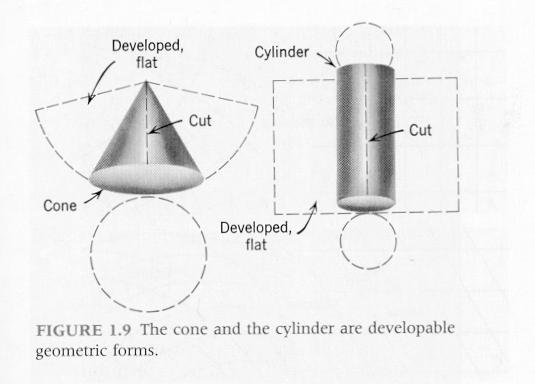
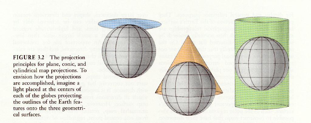
The reason why projection is necessary is that the globe, or any sphere, cannot be made to lie flat without distortion. Imagine trying to wrap a basketball in gift paper. If you tried this, you would find that the paper would fold in some places and perhaps tear in others. Any three dimensional object that cannot be made to lie flat in two dimensions without distortions like folding and tearing is called an Undevelopable Geometric Surface or Form. In order to make a map, then, the data on a globe must be transferred to a developable geometric form. Two such forms are shown below.
The three developable surfaces used in cartography are the cylinder, the cone, and an already flat piece of paper or plane. These three surfaces constitute the three major classes of projections, Cylindrical, Conical, and Azimuthal (which may also be termed Zenithal or Planar). These are shown in the following figure.
How to Project:
Although modern projection involves the mathematical transformation of data on a globe to a developable surface, we may get an understanding of the process by imagining a literal process of projection using light. Imagine the globes in the previous diagram to be of plexiglass and that the outlines of the world's continents are drawn in black on the surface of the globes. If a light were to be placed in the center of each globe, shadows of the continents would be cast on each globe's developable surface. If the cone and cylinder were then cut and developed, that is laid flat, there would be the maps.Projection Aspect:
Aspect deals with the orientation of the developable surface relative to the globe. There are three aspects, Normal, Transverse, and Oblique. The diagrams below show these three aspects for Azimuthal, Conical, and Cylindrical projections.
Projection Case:
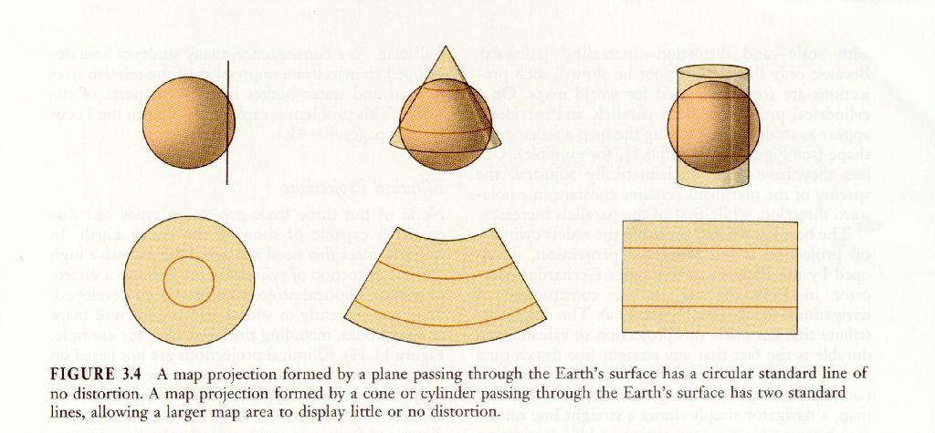
Case deals with the manner ion which the globe and developable surface touch. Important to remember is that wherever the globe and surface touch, NO distortion occurs. There are two projection cases, Tangent and Secant. Tangent case means that the developable surface comes into contact with only the surface of the globe (see below). For the Azimuthal class, tangent case means that the paper touches the globe at a single point. For the Conical and Cylindrical classes, the paper touches along a line. In the secant case, the paper passes through the globe (obviously this must be a mathematical form of projection). The result is that azimuthal maps will have a circle of contact and cones and cylinders will have two lines of contact (see below).

Example of Distortion:
Remember that whenever projection takes place, some form of distortion must occur. The diagram below shows a simple form of distortion.
This is a simple azimuthal/zenithal/planar projection class example. The light coming from a source at the middle radiates outward in all directions, but is blocked out by the points A and B on the surface. A and B cast shadows on the planar surface held tangent at the globe's equator. This would be a tangent case, equatorial (or transverse) aspect, azimuthal projection. Please note that line segment AB is not the same length as line segment A' B'. Distance has obviously been distorted.Controlling Distortion:
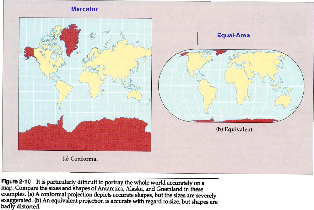
Controlling distortion is always a compromise. It is most important to note that location, distance, direction, shape, and area cannot all be held true on the same map. Shape and Area are the characteristics that are least compatible. Maps that preserve area are called Equal Area maps. While areas will be accurate on such maps, shapes will be distorted. Maps that preserve shape are called Conformal. Conformal maps, however, severely distort area.
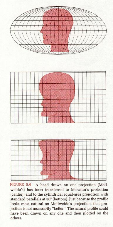
The diagram at left depicts a human head drawn
with true shape and area on one map and then what happens as the image
is projected onto a conformal and onto an equal area map. The
first
projected map is a Mercator, which is a conformal map (we
will look at the Mercator in greater detail later). Notice that the
BASIC
shape of the head is held true, but the area is severely distorted. In
the second instance of projection, an equal area map is shown. The area
of the head is now correct, but the shape has been severely distorted.
Map Pros and Cons:
You need to become familiar with the BASIC pros and cons for each of the major projection classes. What is shown here is the result of great simplification, but is sufficient for our purposes.Azimuthal/Zenithal/Planar Projections:
Cons: The basic con is that a single cone cannot show the entire globe. They will typically show a little more than a hemisphere. Also, conic maps show only a sector of a complete circle…they don't develop into a complete circle.
Cons: These still cannot show ALL of the earth's surface.
Focus on the Mercator:
The Mercator projection is a conformal, cylindrical projection. This particular projection dates from 1569 and was introduced by a Flemish mathematician/cartographer, Gerardus Mercator. The aim of Mercator was to produce a world map suitable for navigation. To see why this map is good for navigation, we must first have control over a set of concepts.Our attention will now turn to working with the Mercator projection.Concepts:
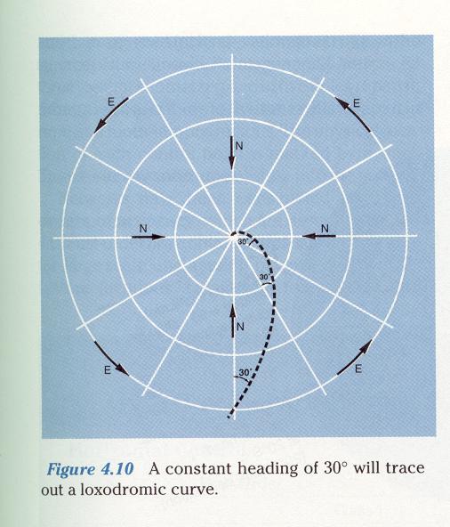
Rhumb line or Loxodrome: These are lines of constant compass bearing. If a line is of constant compass bearing, the line will cross meridians as a constant angle as shown in the following diagram. The diagram shows a Loxodromic Curve which is, of course, of constant compass direction. One could not navigate on this curve since constant course correction would be necessary. We will see later how this problem is overcome using the Mercator.
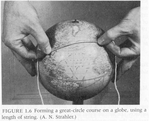
Great Circles and Great Circle Routes. A great circle is the smallest possible "hoop" that would fit completely around the globe. There are an infinite number of such "hoops," and they may be oriented any which way imaginable. This means that any two points on the surface of the globe may be connected by moving one of these "hoops" until it passes through both points. An important fact is that the shortest distance between any two points on the surface of a globe is a great circle route. A great circle route may be determined for any two points on a globe just by connecting the points with the shortest possible piece of string as shown in the following diagram.
Ideally, then, a navigator would like to follow a great circle route because it would minimize travel distance, time, and cost. We will find, however, that great circle routes are seldom straight, navigable lines! We will need a trick to make the Mercator work.
1. Any straight line drawn on the Mercator is a Rhumb line or Loxodrome. This means that any straight line may be navigated upon.
2. Not all straight lines will be the shortest distance between any two points on the globe.
3. Only meridians and the equator are also the shortest distance between any two points since they are all equivalent to great circles.
4. All shortest distance paths other than meridians and the equator are curved so they are unnavigable.
Note that a straight line is drawn between Portland and Cairo. Since this a straight line, it is a Rhumb and therefore navigable. This path would, however, not be the shortest distance between the two cities. If you had a globe in front of you, you could trace this path and see that you would have to travel along the "fatter" part of the globe…that is nearer the equator. There is a second line on the diagram, a curve. This is actually the shortest distance between Portland and Cairo as it is a great circle route. If you tried connecting these two cities on a globe with string, this path would require the least amount. The curved path is not a Rhumb or Loxodrome so one could not navigate upon it. Why then is the Mercator such a good map for navigation?
The following diagram shows how to navigate
using
the Mercator. If the curved path is the shortest distance, but can't be
navigated upon because it is curved, then why not approximate the curve
with a series of straight, navigable, segments? A navigator would take
a heading along the first segment and fly for a certain period of time
and then adjust course to follow the second segment and so on. This is
how to navigate using the Mercator.
Mercator Pros and Cons:
Cons:1. If you look at the previous diagram,
you
will see that the poles are not visible. This means that the Mercator
still
cannot show the ENTIRE globe. 2. Although this is the map you have
worked
with most in your school career, it has lied to you!! One of
the
worst characteristics of the Mercator, being a conformal map, is that
it
severely distorts area. Note the apparent sizes of Greenland and South
America. If you only studied the Mercator, and haven't looked at a
globe,
you would come to the conclusion that Greenland is as large or larger
than
South America. This isn't the case in reality. South American is
actually
8 times the size of Greenland!! Take a look at the following diagram.
The
map on the left is a Mercator…looks familiar doesn't it? This is the
map
you have seen most of your life and it is responsible for giving you
the
impression that Greenland is so big. Now look at the Equal area map on
the right. The shape of Greenland looks strange, but its area is now
correct.